| GB32 Four Speed Epicyclic Self Changing Gearbox. | |
|
|
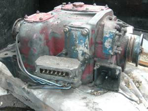
| Right hand side shewing EP valve block & pipes | Left hand side shewing air feeds for brake bands |
|
|
|
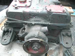
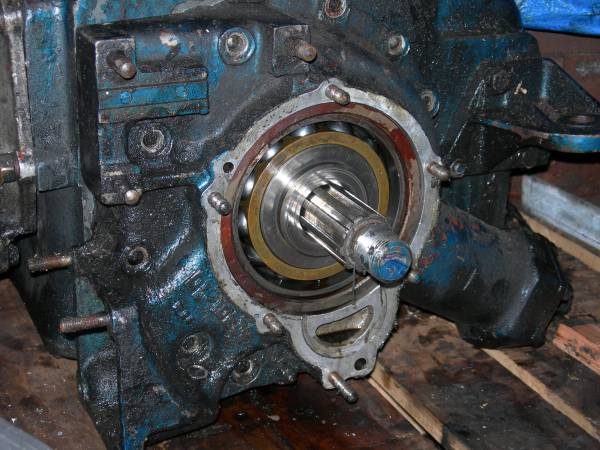
Output flange and ports for Speed Generator
(SG) on left and speedo/tacho on right. |
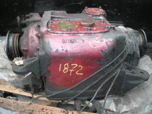
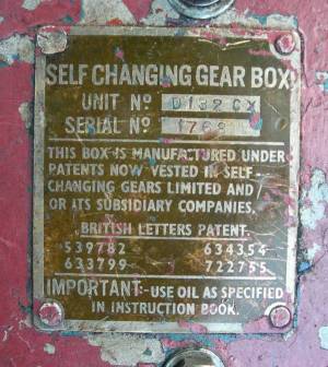
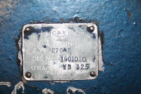
Identification on Gearbox body.
Note it's self changing not automatic! |
| Views of a spare GB32 gearbox without the 'bus "wrapper". This one's a lot grubbier than it should be. | |
The Routemaster has a four speed epicyclic gearbox with electropneumatic
valves controlling pistons which actuate brake bands thereby changing gear.
Fourth gear is a lock-up clutch giving a 1:1 ratio. The actual control
of gear selection is done by the driver's gear selector, a control unit
behind the driver's head and a speed sensor. These notes are based
on RM1872 which has the older CAV system with a Lucas motorcycle alternator
providing the final speed detection. It was this unit which failed
when we drove
RM1872 down to Devon and she's been wired to manual only operation
ever since. The speed generator
has been repaired and so RM1872 will be returned to automatic at some
time. One of the reasons for the delay in doing so was the evidently
poor lubrication of the gear train which may be related to the oil pump
at the front of the 'box being assembled incorrectly and so failing to
provide lubrication! Time will tell.
We also developed a noise on selecting 4th
gear which had to be one of the thrust bearings; probably the one in the
yoke. Examination of the gearbox proved this to be the case and the
race has been replaced.
The Routemaster Owners Association suggests using 2½ imperial gallons of light turbine oil SB 2152 Gearbox or Torque Oil. We have also been told a high quality 15W40 motor oil or straight SAE30 diesel oil with no detergents are suitable. Whilst we cannot recommend a particular oil we are using the SAE30 option because we use it elsewhere on the Railway and buy it in 210 litre drums!
When in service in London the oil would be changed on an annual basis.
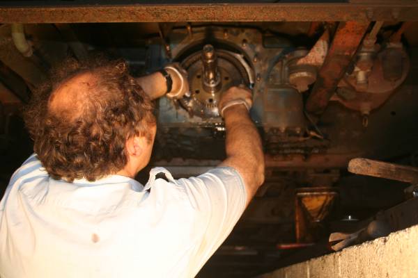
Here are some photographs of the repair operation.
The Routemaster Owners Association suggests using 2½ imperial gallons of light turbine oil SB 2152 Gearbox or Torque Oil. We have also been told a high quality 15W40 motor oil or straight SAE30 diesel oil with no detergents are suitable. Whilst we cannot recommend a particular oil we are using the SAE30 option because we use it elsewhere on the Railway and buy it in 210 litre drums!
When in service in London the oil would be changed on an annual basis.
|
| Refitting clutch plates (RM1872 doesn't have a pre-assembled clutch). |
|
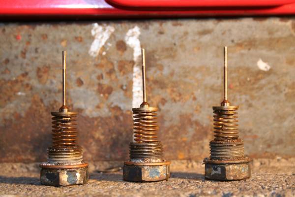
| Clutch Release Springs |
|
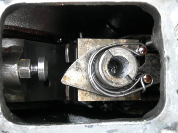
| 4th Gear Thrust Bearing and yoke. Slots top left & bottom right are for the pivot pin and 4th gear piston. |
|
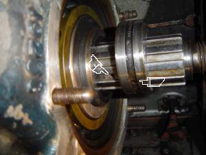
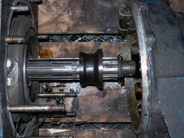
| Cover refitted. Note extra keyway slot (indicated) on input shaft for oil pump eccentric alignment. |
|
| Oil pump eccentric. Holes (indicated) MUST align hence keyway and indicator (face drilling on right). |
The following pictures where taken during the dismantling of a scrap GB32 to see what our problem was likely to be. They're provided here to remind us how it all went together, though it should be noted that we have now discovered the oil pump was assembled incorrectly like the one on RM1872 which probably contributed to both failures! Aligning the extra keyway in the eccentric with the one in the shaft and ensuring the oilway lines up with the hole in the shaft has revealed that the odd drilling in the face of the eccentric has to be towards the pulley. The shaft in the scrap 'box doesn't have the oilway input which also won't have helped! We only dismantled the forward gears because that's all we were interested in at the time. At some point we will strip the rest of the 'box and record what we find here. If we rebuild this 'box then that'll be here too.
 |
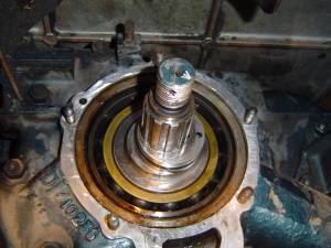
| Outer Thrust race after removing pulley and oil pump; note spacer between thrust race and oil pump |
 |
| Oil pump assembly - note eccentric is the wrong way round (drilling in face should be to outside) |
 |
| Spacer between clutch and front thrust race |
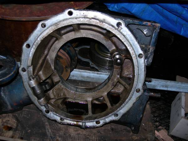 |
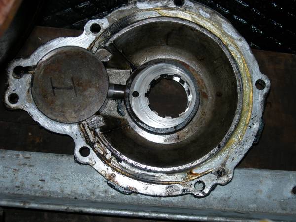
| Inside 4th gear cover; 4th Gear piston bell crank on lower left and yoke fulcrum top right |
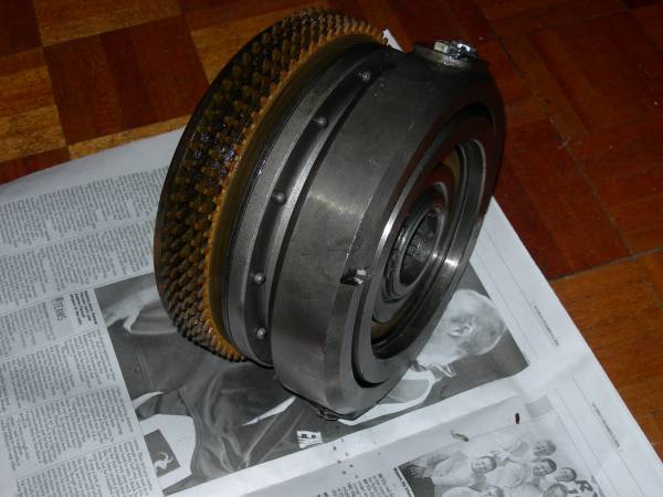 |
| 4th Gear clutch assembly (incompatible with the one in RM1872 apart from the yoke assembly) |
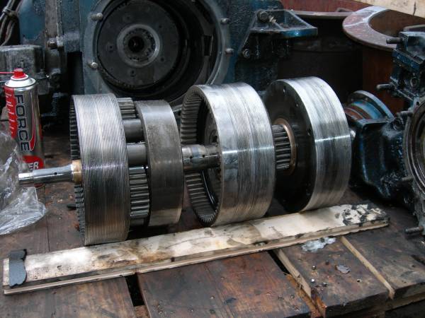 |
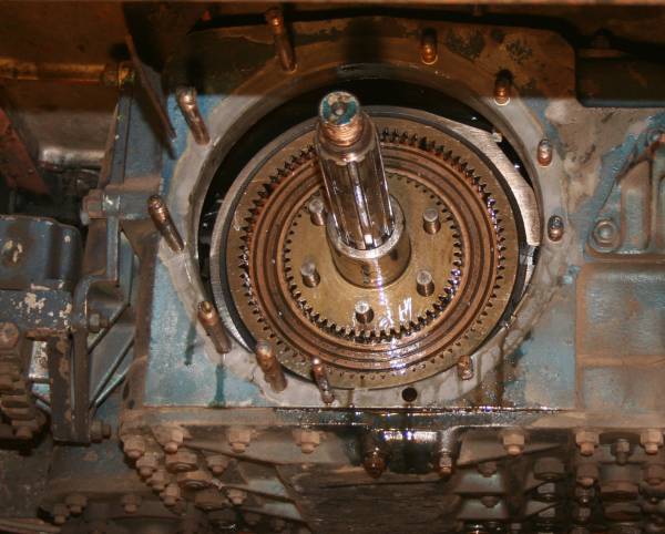
| "Exploded" view of forward gear train - output is on left |
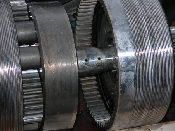 |
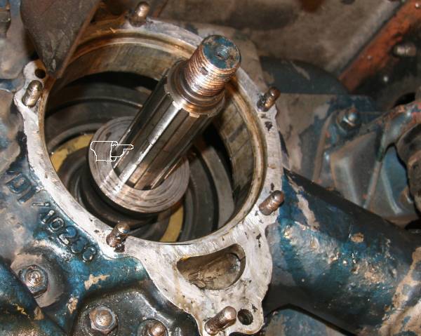
| Note oilways in shaft |
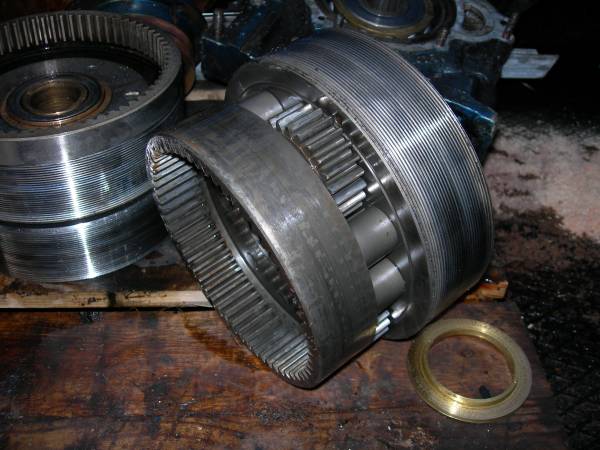 |
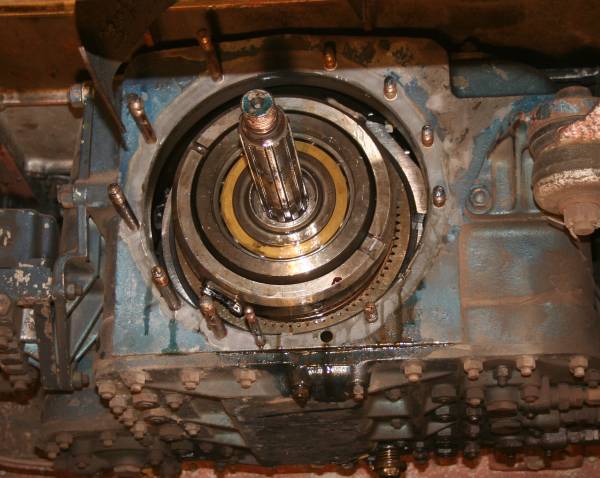
| One of the gear clusters; planet and annulus gears are quite clear. Sun is on the shaft. |
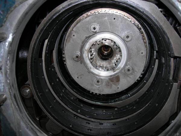 |
| View through the forward brake bands to the final gear cluster |
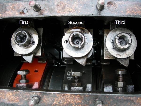 |
| The forward gear brake band adjusters - Note: these come in more than one pattern (see below) |
 |
| The reverse bake band adjuster - note either type can appear in either location |
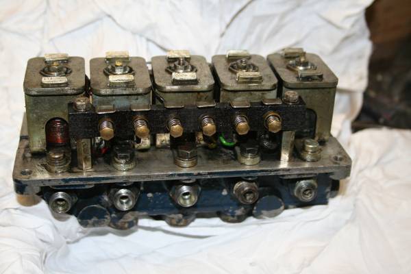
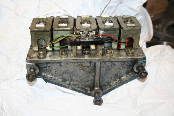
Over the Thomas the Tank engine weekend we "lost" second gear which we traced to the ElectroPneumatic (E.P.) valve block so we changed it for the spare one we have. This fixed the fault. For those who've never seen these important items here are a few photographs.
The solenoids unbolt and contain a shuttle which acts on the spindles
to select the appropriate gear. The system is fail safe in so far
as a wiring break results in no gear being selected. The E.P. valve block
is two wire and should be electrically isolated from the main body.
| Electro Pneumatic (E.P.) Valve Block |
.jpg) |
| E.P. Valve block with spindles removed |
 |
| The E.P. Valve spindles (there are five in total). |
 |
| The E.P. Valve block cover |
 |
| E.P. valve block with cover removed (contacts/relays/ports: common 1st, 2nd, 3rd, 4th & Reverse) |
 |
| Rear of E.P. valve block shewing electrical commoning block |
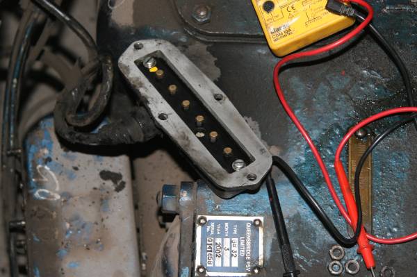 |
| Connector on main 'bus loom |
![]()
© South Devon Railway Trust 2007-11